CNN Digit Detector
A complete end-to-end pipeline that trains a 2D Convolutional Neural Network in PyTorch, exports its weights as fixed-point C++ constants, synthesises the network logic into hardware via Vitis HLS, and deploys the resulting bitstream to an Artix-7 FPGA, displaying live digit recognition over HDMI.
| Target Device | PA-StarLite · Artix-7 XC7A200T (215 K LUTs · 740 DSPs · 13 Mb BRAM) |
| Toolchain | Vitis HLS · AMD Vivado · PyTorch · Python (sklearn) |
| Dataset | scikit-learn Digits containing 1,797 handwritten images (8×8 px, classes 0–9) |
| Interface | Push-buttons · UART debug · HDMI live display (TMDS · 200 MHz diff. clock) |
| Arithmetic | ap_fixed<16,6> (16-bit with 6 integer bits and 10 fractional bits) |
| Clock | 200 MHz differential (DIFF_SSTL135, 5.0 ns period) |
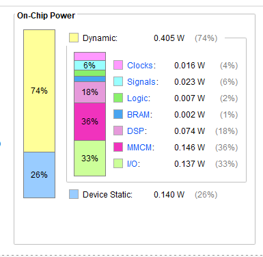
| Dynamic Power | 0.405 W total (DSP 0.074 W · MMCM 0.146 W · I/O 0.137 W) |
Live Demonstration
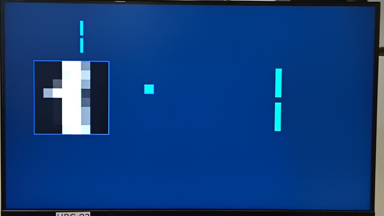
The video below shows the CNN running on hardware, where push-buttons cycle through the stored digit dataset, the 8×8 pixel image is rendered on the HDMI monitor, and the predicted class is displayed in real time alongside the 10-class logit bar chart.
What you are seeing
The CNN bitstream is running directly on FPGA hardware. Physical push-buttons cycle through 1,797 stored digit images. For each button press:
- The selected 8×8 pixel image is fetched from on-chip BRAM and fed to the CNN accelerator.
- The hardware completes a full forward pass (Conv → ReLU → MaxPool → FC) in a single clock burst at 200 MHz.
- The HDMI output renders the pixel grid (left panel) and a 10-class logit bar chart side-by-side on the monitor.
- The tallest bar identifies the predicted digit class in real time, with no CPU involved after the AXI handshake.
Video is muted and loops automatically. Use the controls to pause or scrub.
CNN Hardware Architecture
The forward pass is a three-layer network: a 3×3 convolution with ReLU activation, a 2×2 max-pooling, and a fully-connected linear classifier for 10 digit classes. All intermediate buffers are dual-port BRAMs partitioned across channel dimensions for II=1 pipelining. In HLS, each block becomes physical hardware, including multipliers, adders, comparators, and Block RAMs, all operating concurrently.
CNN hardware dataflow showing three pipelined stages. BRAM buffers (cylinders) hold intermediate feature maps, and all loops run at II=1 with full channel unrolling.
HLS Design
The CNN function is described in C++ with HLS pragmas. Key optimisations: full channel-loop unrolling (4 parallel convolution engines) and complete array partitioning on the BRAM buffers so all four channels can be read or written in a single cycle.
HLS compilation flow: PyTorch trains the model and exports fixed-point weights; Vitis HLS synthesises the C++ forward pass to RTL; Vivado places, routes, and generates the bitstream.
// Channel loop unrolled → 4 parallel hardware convolution engines
conv_label_oc: for (int oc = 0; oc < 4; oc++) {
    #pragma HLS UNROLL
    for (int r = 0; r < 8; r++) {
        for (int c = 0; c < 8; c++) {
            #pragma HLS PIPELINE II=1
            // 3×3 kernel accumulation with zero-padding
        }
    }
}

data_t conv_out[4][8][8];
#pragma HLS ARRAY_PARTITION variable=conv_out complete dim=1  // all 4ch in parallel
RTL Architecture
The HLS synthesis generates a Verilog hierarchy under cnn.v, orchestrated by a 20-state Control FSM that schedules overlapping convolution and pooling to maximise utilisation: one filter pair convolved while the previous is being pooled.
RTL hierarchy generated by Vitis HLS. The FSM (inset) overlaps convolution and pooling in States 2–10, pre-loads FC registers in States 11–19, then runs 10 dot products in parallel at State 20.
Hardware & Results
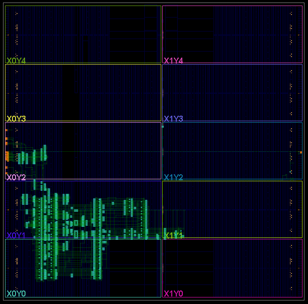
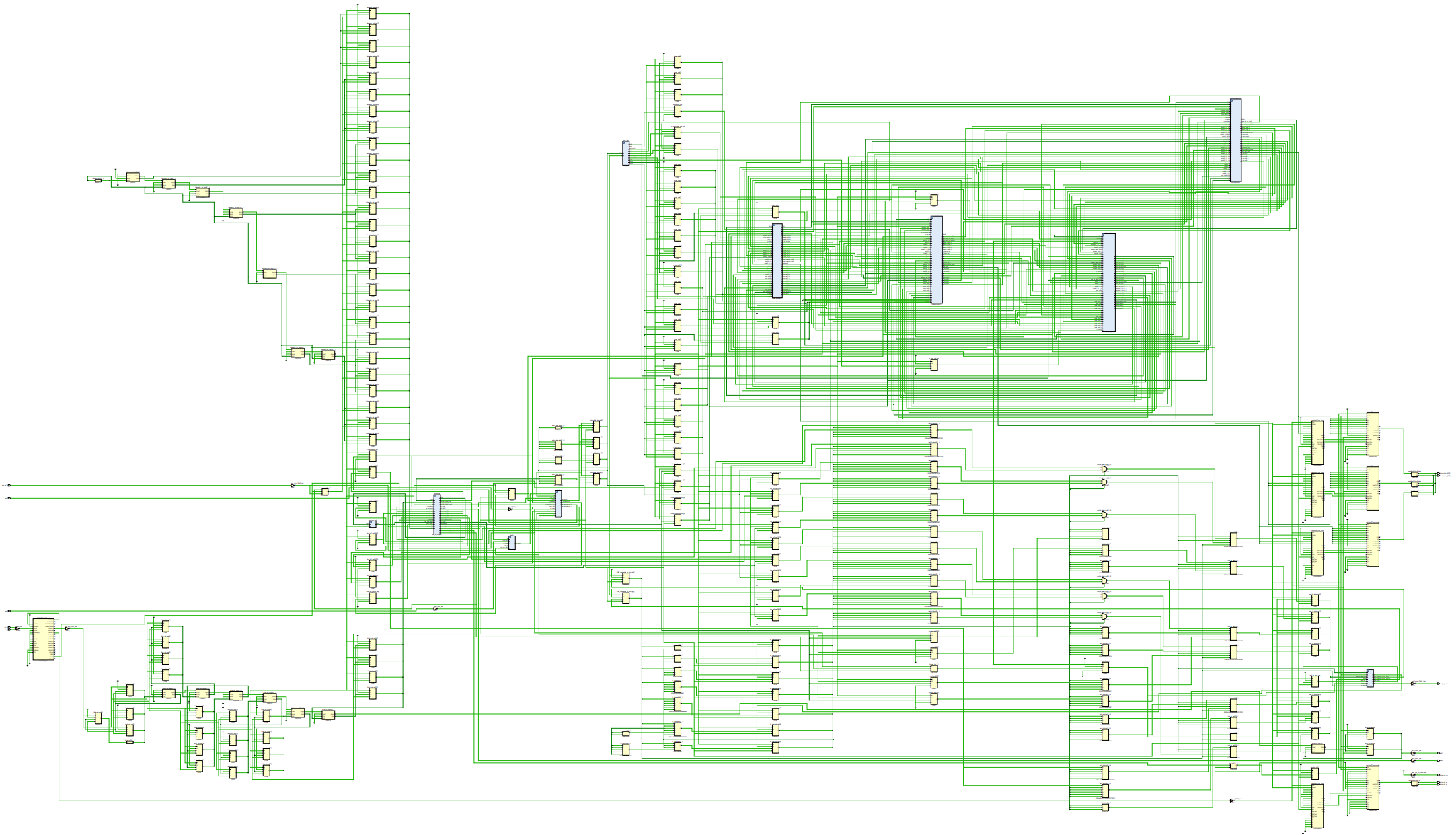
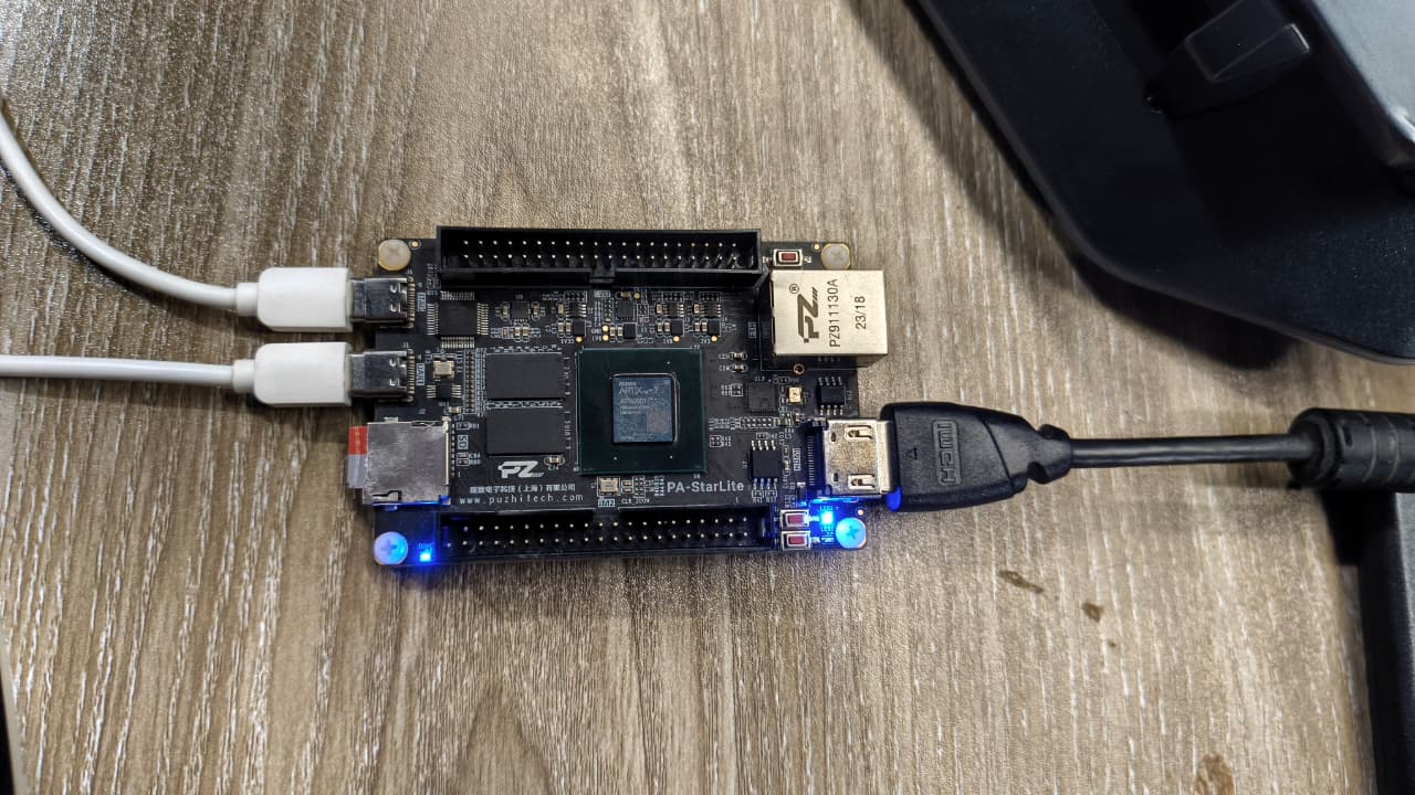
cnn.v top-level wrapper showing ROM, BRAM, DSP MAC block connections, and HDMI output stage.Implementation Summary
| Metric | Value |
|---|---|
| Clock Frequency | 200 MHz (timing closure achieved, no negative slack) |
| Pipeline II | 1 (both convolution and pooling spatial loops) |
| FSM States | 20 (overlapping CONV/POOL + parallel register pre-load) |
| Dynamic Power | 0.405 W (MMCM 0.146 W · I/O 0.137 W · DSP 0.074 W) |
| Arithmetic | ap_fixed<16,6> (bit-accurate co-simulation matches PyTorch FP32 outputs) |
| Weight storage | 64 fc_w ROMs + 1 fc_b ROM + conv_w/conv_b constants in LUT fabric |